I’m utilizing the 4-Channel I2C 4-20mA Current Receiver (PR33-15) with a tri-axial industrial accelerometer (IAC-I-03-2) and having issues identifying a clear signal from any of the axes.
I’ve set up independent power for both the receiver (12V, 1.25A) and the accelerometer (24V, 1A) as instructed by the NCD wiring page.
I’ve connected the +/- power wires to the accelerometer wires (brown, white respectively) and paralleled the - power wires to each of the - terminals on the PR33-15.
I’ve connected the accelerometer 4-20 signal wires (green, yellow, grey) to the + terminals on the PR33-15.
What I measure then, is around 15 mA on all three channels with the tri-axial accelerometer lying flat on the floor. If I move the accelerometer, say to pick it up and twist it in the air, the signal actually drops to around 9 mA.
IAC-I-03-EN-Rev2p4.pdf (1.0 MB)
What am I doing wrong here? What am I missing?
can you share the sensor datasheet.
what the the meter read when you move the sensor. Keep in mind the current will change when the sensor is moved because the change in current indicates the acceleration values.
The sensor data sheet is attached between the two pictures above.
The sensor website is here:
https://micromega-dynamics.com/products/recovib/industrial-accelerometers/
Your wiring does looks correct.
does all channel read same when the sensor is in motion ?
what does the meter read ?
No, actually the channels read different mA values for the same accelerometer motion. The rest values are still elevated (11+ mA) though and none return to 4 mA as expected.
I realized just this morning that the accelerometer is quite hot after leaving it powered up all night. I wonder if I burned up this sensor with a missed wire somewhere.
Any other ideas?
what does the multi-meter read in you connect it in series with any one of the axis?
Thanks
23.5 VDC on any axis (resting)
24.0 VDC on supply
Edit: I’m now working with a new accelerometer. Same make and model.
2nd edit:
The above multi-meter measurements were taken with the axis signal wires disconnected from the PR33-15. When they are all connected as shown in the wire drawing above, the multi-meter reads 2.9 VDC on CH1, 3.7 VDC on CH2, and 2.9 VDC on CH3.
From the manufacturer of the tri-axi sensor:
• Power Supply (24Vdc) connected to the Brown (+) and White(-) wires.
• Each current channel wires (Yellow(X), Grey (Y) and Green (Z)) connected to your board positive current input (CI x +)
• Your board negative current input (CI x -) connected to the power supply ground.
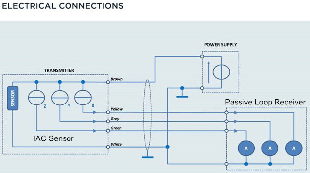
Does this look like it matches my drawing above of how I actually wired the tri-ax sensor into the PR33-15? The only question still in my mind is regarding the last bullet point and the connection to power supply ground. I’m not sure how to do that exactly.
Thanks,
Courtney
Hi,
All 4-20mA "-Ve " from the board will connect to supply ground.
Thanks


