8 Channel ADC ProXR Lite
ref: your page ProXR Quick Start Guide - NCD.io
We are successfully open/closing relays 1-8 per 2.1 Relay Control Commands
Thus we are using correct socket protocol & management.
We are successfully reading status of individual relays.
We wish to read status of all 8 relays at once
per your row in 9.1 Relay Power-up and Status Map
AA 03 FE 7C 00 — 27 Read the Current Status of Relay Banks 1-32 AA 23 32x CK
we send (this is our hex representation, actual bytes are sent):
\xAA\x03\xFE\x7C\x00\x27
we receive
Raw socket input fragment, len=4: AA 01 02 AD
but we should receive:
AA 23 32x CK
the response AA 01 02 AD is not documented anywhere on that page
What are we doing wrong? Thank you.
The command to read the status of all relays in bank 1 is:
AA 03 FE 7C 01 28
This command should respond back with this if all relays are off:
AA 01 00 AB
The third byte there is the status 00.
In these packets AA is a header byte. The second byte in the packet is the length of the payload, and the last byte is the checksum.
Thanks for the weekend reply, Travis.
Yes we do understand API packet structure but thanks for being sure.
In more testing to properly respond to your reply, we have these observations (once we figured out the status encoding) - all in section 9.1:
- We did not understand the use of the first command “Read the Current Status of Relay Bank 1” – your documentation is incomplete. Enhancements needed:
- Define that byte 3 is a bit encoded status of all relays, with relay 1 least significant bit. That should be in your legend above as e.g. “SB” and in the command row as SB, not a constand 0.
- Define the last byte as a variable CK - the “AB” infers it is a constant
- Your description for row “Read the Current Status of Relay Banks 1-32” says it always returns 32 bytes of status (which we thought we needed to read per the above misunderstanding). That is incorrect:
- On our 8 relay board, it returns a single byte with the “SB” bit-encoded 8 values.
- It does not return 32 bytes. And it returns evidently only the bytes required to report on the installed board(s).
-
We will evaluate now use of the commands in “2.6 Set the Status of All Relays in Selected Bank” with this understanding. Note that in that section’s doc, you use the word “Pattern”, not explaining that it’s the status bit-encoding we discovered in #1 above.
-
We indeed find useful your multiple example rows in each section. However, it will be much easier to grok quickly if the first row or so are the generic description, where hex/decimal numbers are only for constants, & you use SB, CK etc for variable values.
-
Incidentally, your Web-i interface does not reflect relay status, all are ‘off’. But the buttons do turn relays on & off.
You can close this issue now, we are reading what we need. Thanks again.
Hi @iicacct
I will see about getting the documentation updated to address your comments for points 1, 2, 3, and 4.
As for point 5 you need to set the work as setting in the NCD5500 module from TCP server to WEB-i in order for the relay status indicators to reflect the status of the relays. That is covered in the NCD5500 user guide I believe. Just set that and the status indicators should work.
Thank you in advance for doc updates.
Re your response on #5:
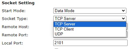
- There is no “WEB-i” mode. See below and attached screenshot.
- It would not be usable to switch modes from operational (TCP server) and another mode simply to see that status. – Not a requirement but would have been handy. During dev we look over to the board

From NCD5500 user guide :
Connection
These settings determine how Software will communicate with the Gen 3 module in daily use. Socket connection type may be selected from the Work As drop down menu. Options are TCP Server, TCP Client, or UDP. In TCP Server mode the Gen 3 module will accept TCP socket connections from your Software over the port specified in the Local Port Field. In TCP Client mode the Gen 3 module will automatically establish a TCP socket to a server on the IP specified in the Remote Host Field on the port specified in the port field to the right of the Remote Host field. Lastly UDP mode causes the Gen 3 Module to utilize UDP sockets. This is a good option if the board needs to send information to multiple software applications running on different servers.