My goal is to know the power consumed for some business servers running in my house.
Also, I updated the original drawing, for clarity.
Load Group 1 (Personal Use) = CKT1, CKT2, CKT6
Load Group 2 (Business Use Servers) = CKT3, CKT4, CKT5
My plan was to determine
- the power used for all circuits (total) in the distribution panel
- the power for each circuit in load group 2 (CKT3, CKT4, CKT5)
- the power used for all circuits (total) load group 1
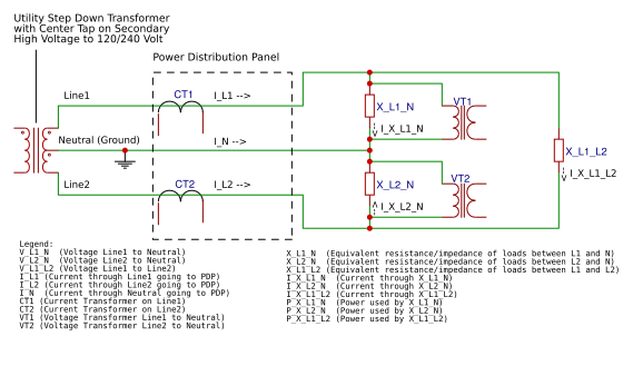
After some more thinking and calculations, @Travis you are correct, I only need 2 VTs and 2 CTs.
The above schematic can be simplified as:
Calculate total power going through PDP
P_PDP = P_X_L1_N
       + P_X_L2_N
       + P_X_L1_L2

P_PDP = V_L1_N * I_X_L1_N
       + V_L2_N * I_X_L2_N
       + V_L1_L2 * I_X_L1_L2
Let
V_L1_N = 120 VAC RMS
V_L2_N = 120 VAC RMS
Because V_L1_N and V_L2_N are 180 degrees out of phase
when V_L1_N is max (120V*SQRT(2)=169.7V), V_L2_N will be min (-120V*SQRT(2)=-169.7V)
therefore the RMS voltages can be added together.
Let
V_L1_L2 = V_L1_N + V_L2_N
V_L1_L2 = 240 VAC RMS
Substitute V_L1_L2 for (V_L1_N + V_L2_N)
P_PDP = V_L1_N * I_X_L1_N
      + V_L2_N * I_X_L2_N
      + (V_L1_N + V_L2_N) * I_X_L1_L2
Multiply (V_L1_N + V_L2_N) by I_X_L1_L2
P_PDP = V_L1_N * I_X_L1_N
      + V_L2_N * I_X_L2_N
      + (V_L1_N * I_X_L1_L2) + (V_L2_N * I_X_L1_L2)
Gather common terms for V_L1_N and V_L2_N
P_PDP = V_L1_N * (I_X_L1_N + I_X_L1_L2)
      + V_L2_N * (I_X_L2_N + I_X_L1_L2)
From diagram, observe that
I_L1 = I_X_L1_N + I_X_L1_L2
I_L2 = I_X_L2_N + I_X_L1_L2
Substitute 2 equations above into P_PDP equation
P_PDP = V_L1_N * (I_L1)
      + V_L2_N * (I_L2)
Rewrite P_PDP equation using current and voltage transformers
P_PDP = V_VT1 * I_CT1
      + V_VT2 * I_CT2
Only 2 VTs and 2 CTs required to calculate total power through the PDP.
Load Imbalances
So what happens if the loads in the PDP are not balanced between line1 and line2 ?
Answer: There will be current flowing through neutral wire (I_N), however the calculated power for the PDP will not be affected because the extra current flowing in the neutral will also be seen in either line1 or line2.
For example, if there is heavier load on line1, the differential current between line1 and line2 flows through the neutral wire to balance the circuit. This extra current also flows though line1 and will be observed by CT1, so the imbalance is captured perfectly.
I_N depends on ratio of X_L1_N to X_L2_N
I_N = I_L1 + I_L2 (I_L1 and I_L2 point in opposite directions, so adding them will effectivly be the difference)
When X_L1_N = X_L2_N
then I_N is 0
When X_L1_N < X_L2_N
then I_N is Neg on first 180 degrees of waveform
and I_N is Pos on last 180 degrees of waveform
When X_L1_N > X_L2_N
then I_N is Pos on first 180 degrees of waveform
and I_N is Neg on last 180 degrees of waveform
So in summary, yes, only 2 VTs (VT1 and VT2) and 2 CTs (CT1 and CT2) are required to measure the total power flowing through the power distribution panel.
Measuring individual circuits/branches
When measuring the individual circuits, no new VTs are required. I do not need a VT between Line1 and Line2 because V_L1_L2 = V_L1_N - V_L2_N. So I know the 3 required voltages in the system.
I see an individual CT is required for each circuit I want to know the power consumption.
Product recommendations
So which product would you recomment to measure the 2 VTs and 6 CTs (2 CTs for the mains and 4 CT’s for some branch circuits) ?
I would prefer to use 1 board that has VT and CT measurments and does power calculations on the board. Doing VT measurement on one board and CT measurement on another and then doing the math in a raspberry PI, would provide a source of error, especially if power factor is far from 1.0.
Thank you,
-Mark


