I have 2 PDUs that were made for the same set of outlets but that used different relay boards.
The first used
one NCD ZUXPR16X0PROXR a 16 channel controller
one 4 relay expansion (unknown part number)
The second used
one PR60-68_XR820 8 channel controller
two ZUXPR820PROXR 8 channel expansions
Our customer wrote programming for the first unit based on its banking configuration. They are saying that the programming doesn’t work on the second unit.
My question is whether the banking of a set of boards can be configured independent of the actual boards. In other words can I make the 16 relay board and 4 relay board look like two 8 relay boards and the first 4 relays of a third in terms of banking?
Yes, as far as software is concerned the API sees no difference between 16 channel on a single board and 8 channels on two boards provided one is an expansion board.
It looks like you my have the expansion boards and master boards switched as the XR820 is an expansion board and the ZUXPR820PROXR is a master board with a communication interface.
But is the banking configurable? I mean can 1 configure the 16 relay control board to recognize the first 8 relays as bank 1 and the second 8 relays as bank 2
The banks are not configurable. I’m not 100% sure what you mean, but the bank numbers are determined by their relay driver’s position on the bus. So for a 16 channel board bank 1 will always be bank 1 as they’re considered the first relays on the bus, the bank 2 relays will always be in bank 2, and an 8 channel expansion board will always be bank 3 unless there’s another XR board in front of it on the XR Expansion chain in which case it would come after the last bank of the last board on the XR Expansion chain.
i.e. a 16 channel proxr board would have banks 1&2, an 8 channel XR expansion board would be bank 3 attached would be bank 3.
If you have two 4 channel expansion boards connected to a 16 channel ProXR master board then the two expansion boards would each be their own bank as the relay driver chip that each will have is what really determines the bank.
Concerning relay numbering in a bank. If I have 8 relays in 2 columns are the relays numbered (from top to bottom) 1-4 in the first column and 5-8 in the second column?
Sorry for the question as I am sure they are labeled, but I don’t have any boards and haven’t found a photo where I can read the labels.
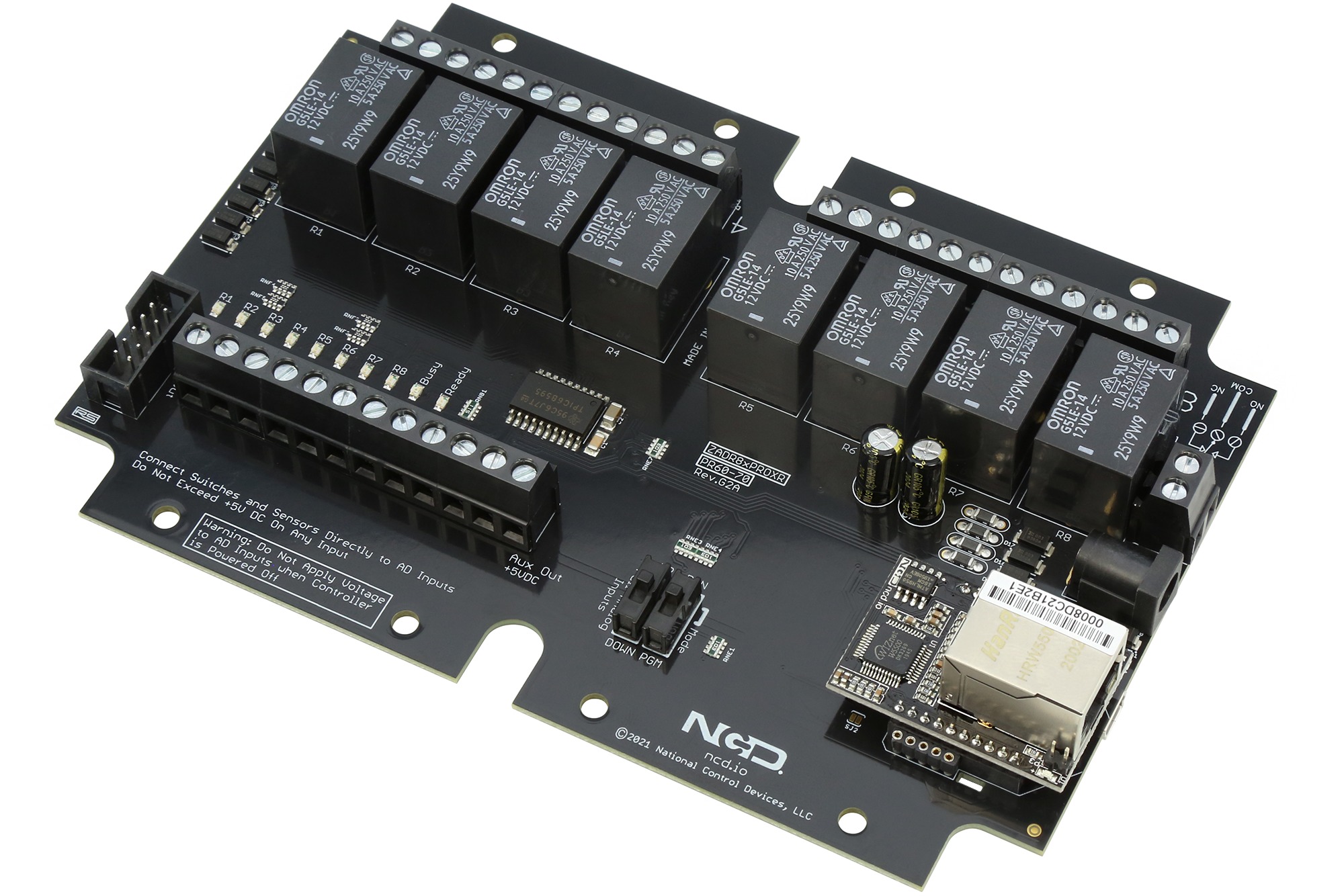
It depends on the board how the labeling works, some are labeled R1 through R8 with an indicator next to the particular relay (i.e. https://media.ncd.io/sites/2/20210325140937/PR60-70_A_ETHERNET.jpg) while some are labeled 1 on one side of the terminal block and 4 on the other to indicate that the relay next to 1 is the first relay in the bank and the relay next to 4 is the fourth relay bank and the relays in between are 2 & 3 in the order you would expect (i.e. https://media.ncd.io/sites/2/20240513133041/ZADSR32xPROXR_USB.jpg) with a repeat of the sequence for the next 4 relays being labeled 5 & 8 on each side of the terminal block.
Not a problem, let me know if you have any other questions.
Is there any possibility that I could get a diagram of the ZUXPR16X0PROXR indicating its relay numbering? I have found pictures of the newer boards indicating their numbering. I am looking at photos to try to evaluate the wiring of PDUs made from the two different sets of boards to verify that they are the same. Having the relay numbering information would be a big help
